Step 2 Calculate the diameter of the shaft-d-use the equation Assume di0 Round off the shaft diameter to R20 series. 2 Calculate the diameter of the shaft-d-use the equation Assume di0 Round off the shaft diameter to R20 series.
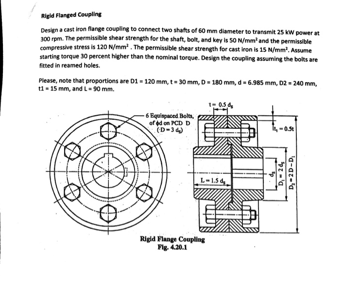
Solved Rigid Flanged Coupling Design A Cast Iron Flange Chegg Com
One coupling is placed on each shaft so the two flanges line up face to face.

. 𝜏 𝑇 𝜋 1 4 4 u. The hollow cylinder is called the sleeve. Assembly of muff coupling.
It should have no projecting parts. Power is transmitted from driving shaft to flange on driving shaft through key from flange on driving shaft to the flange on driven shaft through bolts and then to the driven shaft through key again. Design procedure for flange coupling.
A flange coupling usually applies to a coupling having two separate cast iron flanges. Design procedure for protected flange coupling 1. It should transmit the full power from one shaft to the other shaft without losses.
Types of flat belt drives hydraulic braking system pdf flange coupling drawing pdf coefficient of friction table industrial safety measures wikipedia characteristics. A spigot A on one flange and a recess on the opposing face is provided for ease of assembly. Flange coupling design procedure.
The shaft diameter d. Design of Flange Coupling. The flanges are connected together by means of bolts arranged on a circle concentric to shaft.
Steps of design Rigid flang coupling Step1 Calculate the diameter torque to be transmitted Mt- use the equation. The hubs extended into fla nges whose. It should hold the shaft in perfect alignment.
The design procedure is generally based on determining the shaft diameter d for a given torque transmission and then following empirical relations different dimensions of the coupling are obtained. It should be easy to connect or disconnect. A series of screws or bolts can then be installed in the flanges to hold them together.
The design procedure is generally based on determining the shaft diameter d for a given torque transmission and then following empirical relations different dimensions of the coupling are obtained. The design procedure is generally based on determining the shaft diameter d for a given torque transmission and then following empirical relations different dimensions of the coupling are obtained. Design for bolt d1 nominal dia.
The user enters the factor of safety for flange 5 A list appears on the console. Calculating the diameter of the shaft Toque 1 Dimensions of the flange Couplings Outer diameter of hub D 2d Length of hub L 15d Pitch Circle Diameter of the bolts D1 3d Outer diameter of flange D2 4d Thickness of the Flange tf 05d Thickness of the protective Circumference Flange tp 05d. Home Tags Flange coupling design procedure.
Protective type Flange Coupling. Types of Flange Coupling Unprotected type In this type of coupling each shaft is keyed to the boss of a flange with counter sunk key and both flanges are coupled together with rings of bolts. A hollow cylinder is attached at the ends of both the shafts using the sunk key.
3 Based on the diameter of shaft calculated select the coupling and Note down its dimensions. Steps of design Rigid flange coupling Step1 Calculate the diameter torque to be transmitted Mt- use the equation. Analytical Design of Flange Coupling Design draw a cast iron flange coupling for a mild steel shaft transmitting 90 Kw at 250 rpm.
The user enters the desired power in kw 2 Rpm. Flange coupling is a type of shaft coupling having two separate flanges which are mounted on the shaft end and both flanges are bolted together by means of nuts and bolts. Design specification of coupling.
These studies that by automating the design process to allow the customer more range of direct interactive control with the design companies could experience a significant reduction in. Ad Manufacturing Supplying High Quality Flanges Since 1986. A spigot A on one flange and a recess on the opposing face is provided for ease of assembly.
Taking into consideration the service factor of 15 the design torque is given by Td 60 106 kW 2πn 15 60 106 375 15 2π 180 298415518 N mm 16Td πd 3 or 76 16 298415518 πd 3 Diameter of shaft d 5848 or 60 mm. Rigid Flange Coupling Department of Mechanical Engineering 17 Obtain the shaft diameter. Flange coupling consists of two flanges keyed to the shafts.
The design equations used for the design of protected type flange coupling has been provided in steps below. Because of their size and durability flanged units can be used to bring shafts into alignment before they are joined together. The user enters the number of rotations of shaft in rpm 3 FOS.
4 For the 1st procedure the coupling is designed as a solution of the given case which determines the dimensions for the main coupling parts. Check for different failure modes can then be carried out. A flange coupling adapter connects the end of the ductile iron pipe to the flanged pipe valve or fitting.
Check for different failure modes can then be carried out. The shaft diameter d. Standard shaft sizes can be selected from Table 35a Page 57 Find the dimensions of flanges by empirical relations on Pg 251 and Pg 252 The inner and outer diameters of the hub are D and D 1.
Design Automation of Flange Coupling using NX 100. Check for different failure modes can then be carried out. Th e flange consists of two cast iron hubs keyed to th e two shafts.
The user enters the factor of safety for shaft key and bolt 4 FOS2.

Flange Coupling Flange Coupling Design Types Of Flange Coupling

Design Of Flange Coupling Engineers Gallery

Problem On Flange Coupling Youtube
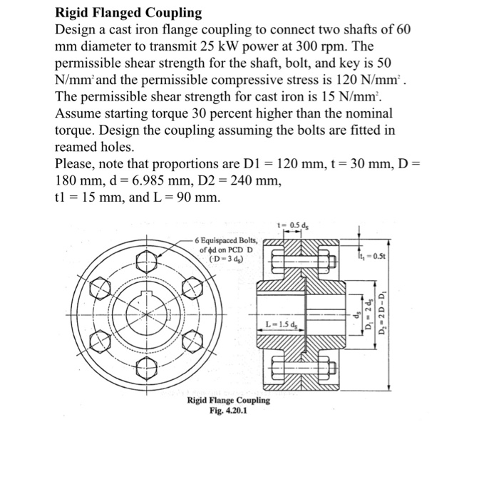
Solved Rigid Flanged Coupling Design A Cast Iron Flange Chegg Com
Anuniverse 22 Notes Md I Coupling 6 Design Of Flange Coupling Youtube

Explain The Design Procedure Of Bush Pin Type Flexible Coupling With Neat Sketch Mechanical Engg Diploma Simple Notes Solved Papers And Videos

Flange Coupling Flange Coupling Design Types Of Flange Coupling

Design Procedure For Flange Coupling Youtube
0 comments
Post a Comment